|
|
Mike's Mini Project - page 11 |
|
|
|
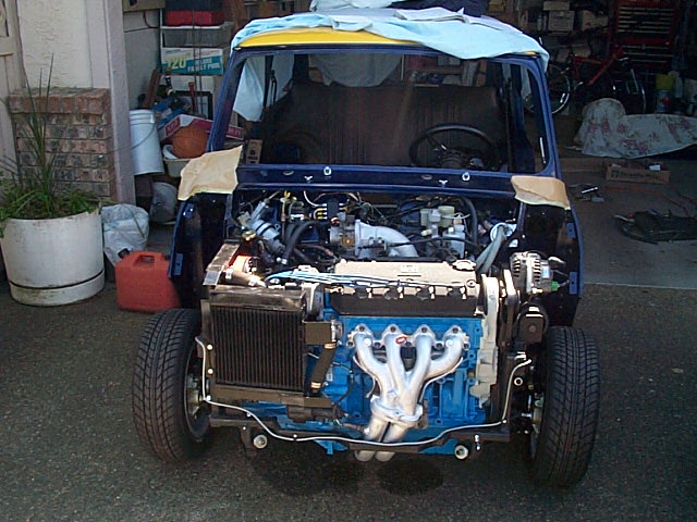
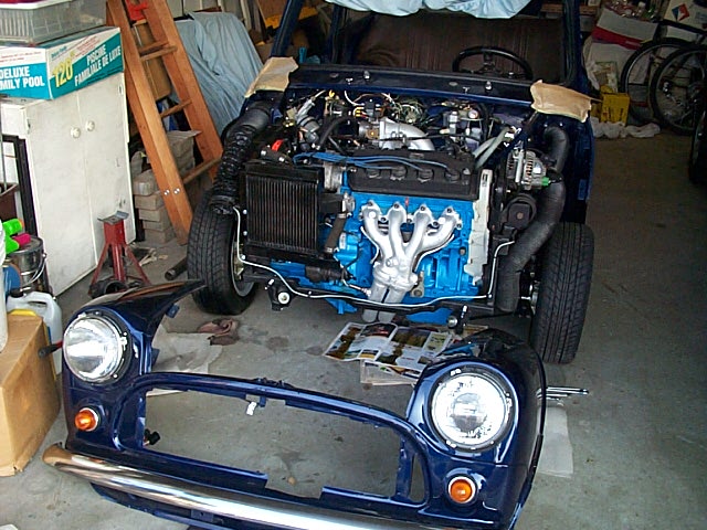
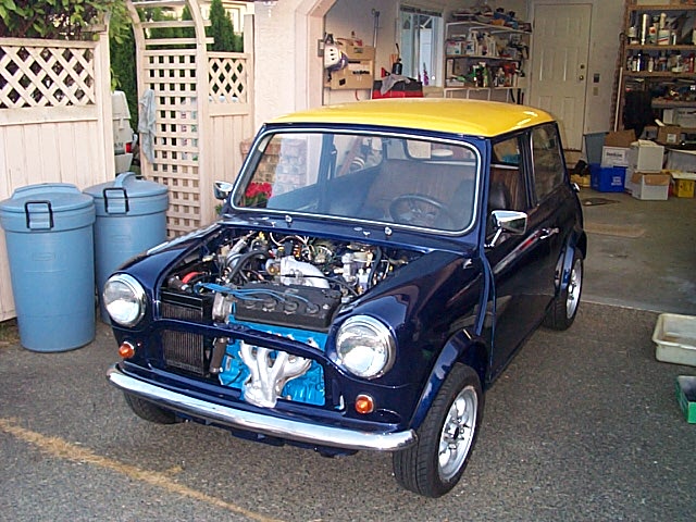
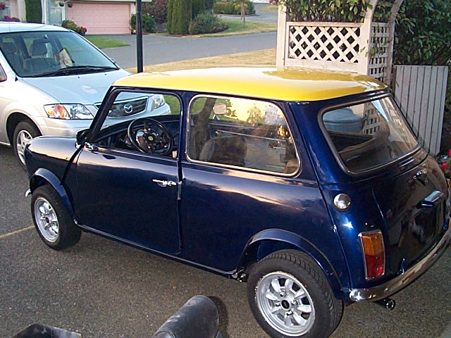
Final assembly of the engine in the car, alternator, drive shafts and radiators going into the car. It's on wheels again! |
|
|
|
|
|
|
|
|
|
|
|
|
|
Home
Mike'
Project | | Page 1 | Page 2 | Page 3 | Page 4 | Page 5 | Page 6 | Page 7 | Page 8 | Page 9| Page 10 Page !!
|
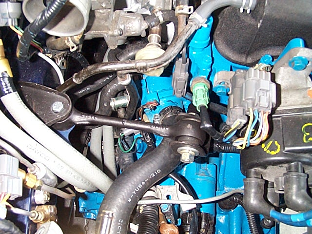
1. The Mini dog bone was used as an engine steady for the Honda as well. A bracket was fabricated for the Honda that bolts to the block using the transmission casing bolts. |
|
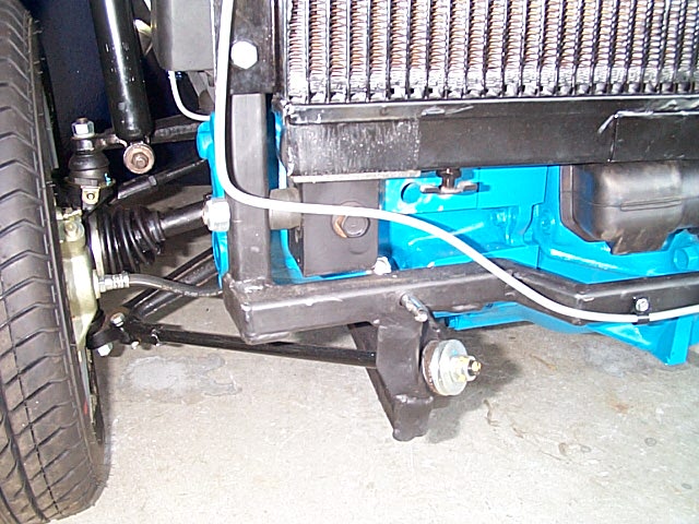
2. Here is the lower engine stabilizer, and there is another one on the other side as well. |
|
|
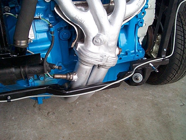
3. A view of the sub frame, which I found I had to move out farther again to properly clear the lower exhaust pipes. |
|
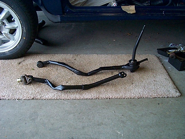
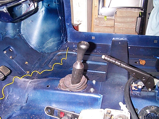
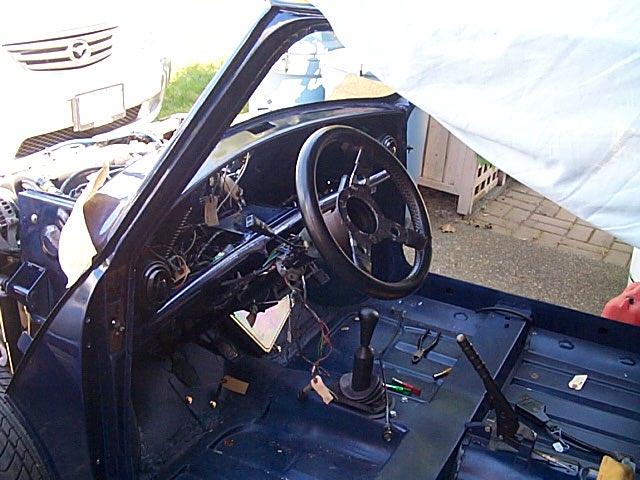
4. The Honda shifter was shortened, and then modified to clear the firewall. The shifter would have come up in the middle of the floor about 12” back of the Mini hole, without the modifications. This took a lot of trial and error to get it to shift smoothly. But the results works well. |
|
|
5. A shot of the Honda shifter coming up through the Mini floor. I was able to use the Honda rubber mounts for the end of the shift linkage, and the Mini shifter boot fits fine! |
|
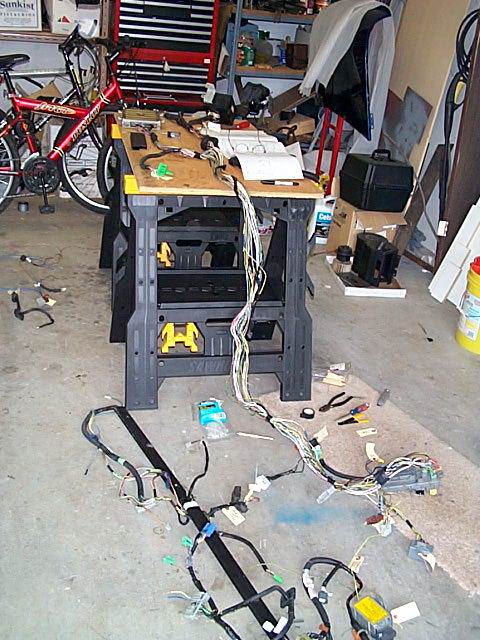
6. This is the wiring phase starting. I removed all the unnecessary wires from the Honda harness, leaving me with only the engine management, starting and charging circuits. I then removed the huge Honda fuse boxes and replaced them small aftermarket ones. |
|
|
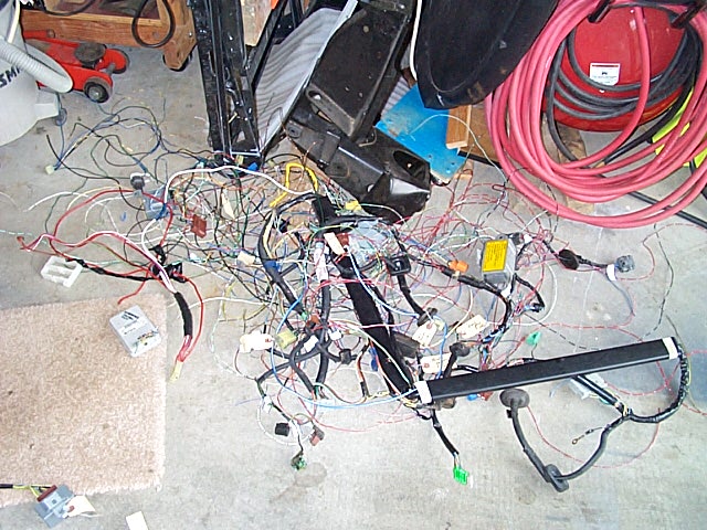
7. Here is all the wire that was culled out of the Honda harness! |
|
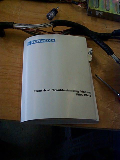
8. The bible. I ordered this electrical wiring manual from
Honda. It took over 3 months to come from |
|
|
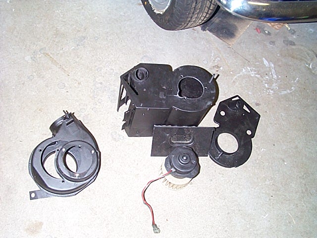
9. The heater motor was removed from the assembly on the left, which used to be mounted under the hood on the inner wing. The inside heater assembly was then cut to accept the motor, just like in the older Minis. |
|
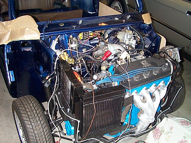
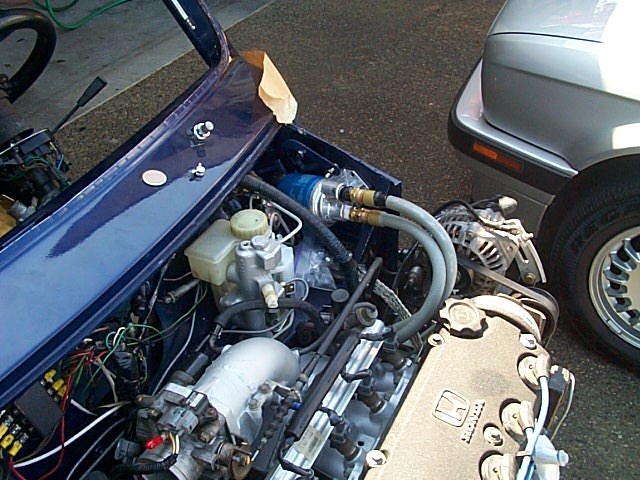
10. A small indication of what’s under the hood! |
|
|
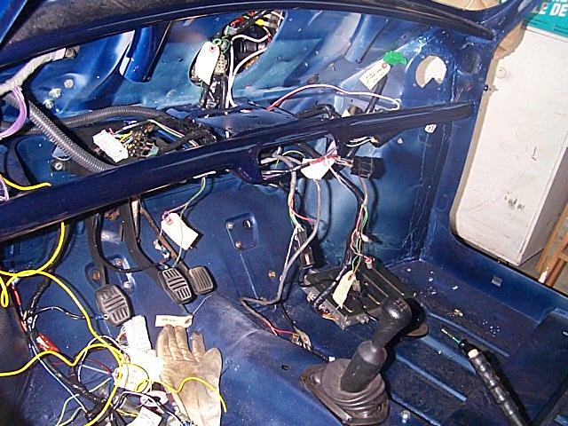
11. Here’s a shot of the wiring harness getting installed in the car. The Mini harness was used for all the lighting, wipers, horn etc, while the Honda harness handled all the engine stuff. |
|
12. I used two waterproof trailer connectors for the connections to the front clip. That way it would be easy to remove if required. |
|
|
13. Both harnesses now installed and tucked away ready for the dash install. |
|
14. This was the big day, I started the engine up and it fired up the first time after filling the fuel lines. You can see a few leaks on the ground which I later resolved.. |
|
|
15. I had to relocate the remote oil filter, due to the radiators, and eventually I removed this altogether as I found I had enough room to change the filter from below. |
|
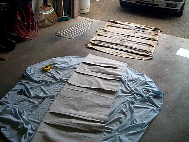
16. The dreaded headliner task starts here. New one in front, old in the rear. |
|
|
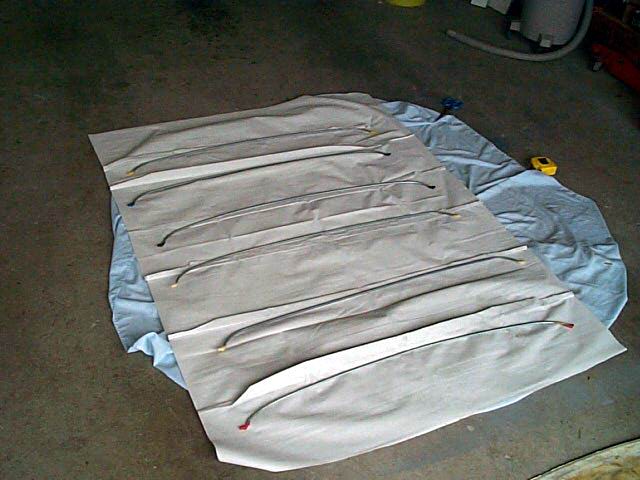
17. Headliner with the bows laid out and ready to start. Each bow is a different length, but they are color coded to make things wasier. |
|
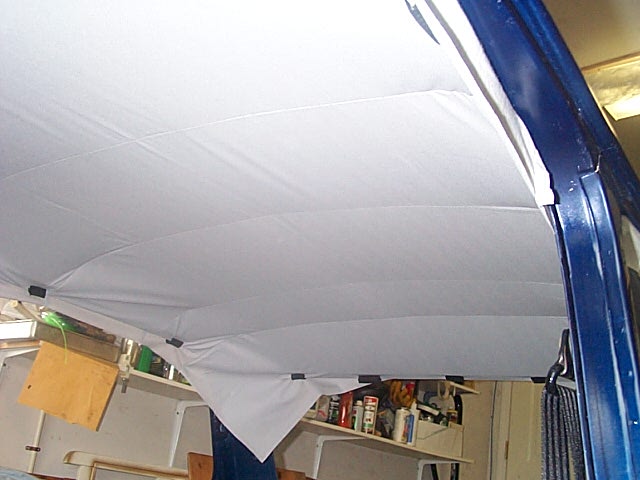
18. A view of the headliner up in place and starting to stretch into a tight install. This took a long time to fuss with and get all the wrinkles out. This shot still shows a lot of wrinkles. |
|
|
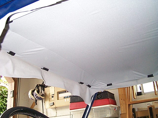
19. Getting better, but still no perfect. |
|
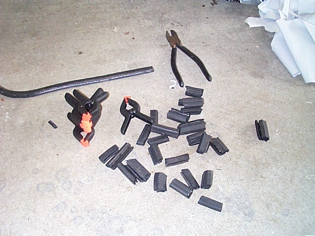
20. The clamps kept popping off as I tightened the headliner, so I cut up old window seals from the rear side windows into 2” pieces and used them to clamp the material. They worked great.. |
|
|
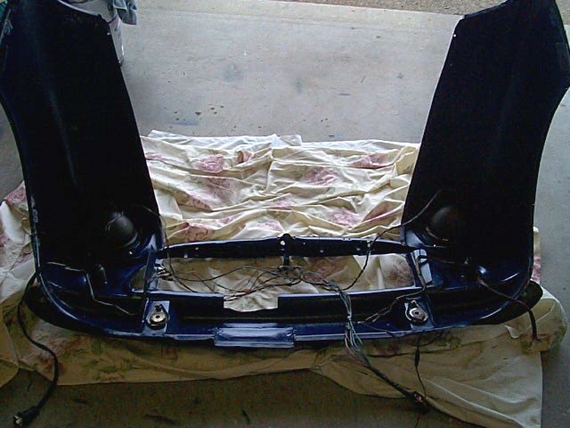
21. The front end gets wired up here. A lot easier off the car like this. |
|
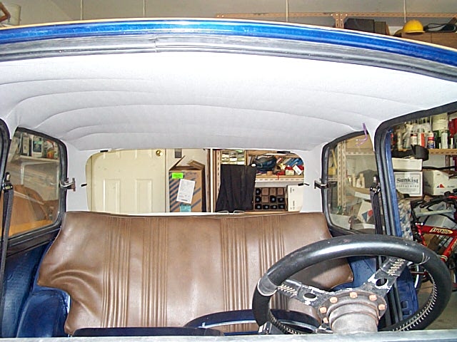
22. A final shot of the finished headliner. I was quite happy with the result, but it took about 6 hours to do by myself. |
|
|
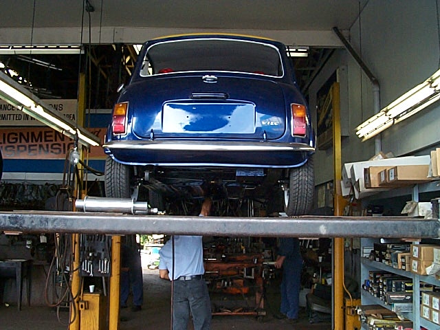
23. Up on the rack for the exhaust system, one that is not too loud, but a slight rumble. |
|
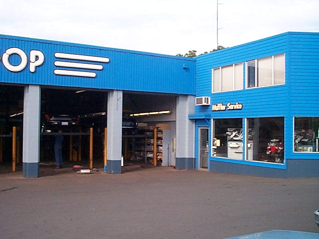
24. I towed the car to the local performance muffler shop. They did a great job and used the Mini hangers for the muffler. A nice chrome tip pokes out the rear right where the stock Mini one goes |
|
|
25. Front end ready to be installed. |
|
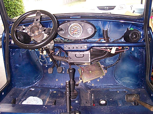
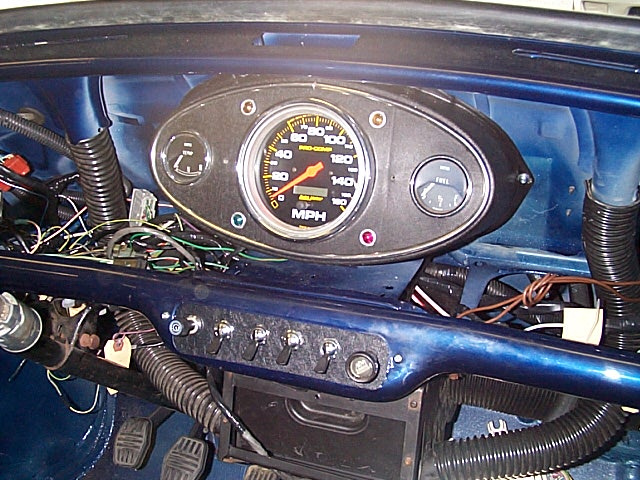
26. Dash, switches and windows now installed. I converted from the newer rocker switches to the old style toggles. |
|
|
27. The 3 clock dash. The speedo is an electronic one that works with the Honda sender, so I lost the gas gauge. I replaced the oil gauge with a gas gauge from an MG, which looks the same, and the oil is no on the Honda ‘oil ‘idiot light’. |
|
|
|
|
|
|
![]()
|
|
|
|
|
|
Home |